mboxler
-
Posts
574 -
Joined
-
Last visited
Content Type
Forums
Events
Gallery
Everything posted by mboxler
-
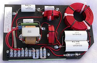
Here is a picture of the ALK Universal that I pulled off his website. In order to wire for bi-amping, you want to bypass the 1.3 mH inductor and the two paralleled 24 uF capacitors (basically, cutting off the right third of the network). As I remember, to do this, you need to remove the two terminal jumpers, connect the negative speaker cable to the fourth screw from the right, and connect the positive speaker cable to the screw that is to the immediate left of the two large capacitors. In your case, there is no easy way to bypass these components, unless you want to do a lot of cutting, rewiring, and soldering.

-
Can you provide a picture of the Universal from the top? Al's instructions were meant for the original universal, and may not work with the economy version. Hopefully there is a screw down post on the back side of the 33uF capacitor. You would connect the + wire from the AP12-xxx mid out to that post instead of the front terminal strip. Have you contacted Al? Mike
-
I've been thinking about a different solution. Replace the 2.5 mH inductor to the K-22-E with a 1.3 mH, then adding an autoformer between the new inductor and the driver. Input 0 - 4, output 0 - 5. This would double the power to the driver...a 3db increase. Not sure if the autoformer would handle the current.
-
I may be wrong, but... Each component of the crossover results in a 45 deg phase shift. The inductor to the woofer...-45 deg. The cap to the mid...+45 deg. This results in a +90 deg phase shift between the two drivers. The third order filter to the tweeter is +135 deg (I think) so it is shifted +90 deg from the mid. Please corrent me if I am wrong.
-
This has always confused me. It seems that the first 2uf cap to the tweeter is in series with the 13uf to the mid. The result would be a 1.75uf cap as the first part of the third order filter to the tweeter. Changing the 13uf to 6.8uf would equate to a 1.5 cap. Would it have been better to run a separate wire from input + to the 2uf cap? Am I missing something?
-
Do you mean this one https://community.klipsch.com/index.php?/topic/144613-chip-amps-almost-everything-you-ever-wanted-to-know/?hl=tda7297
-
$130 shipped. PM me if interested. Mike
-
I have a pair of pristine Crite's CS 400/4500 crossovers I can sell you. I believe the only differences between these and the A/4500 are... 1) The midrange capacitor is 6 uF instead of 13 uF, as the midrange is down 6 dB instead of 3 dB (taps 0 - 3 vs 0 - 4). 2) The tweeter is down 3 dB instead of 0 dB (taps 0 - 4 vs 0 - 5). The 2.5 mH woofer inductor, .5 mH midrange inductor, and 4 uF tweeter capacitor are identical to the A/4500, as I recall. I assume you already have a pair of CT125 tweeters. Let me know if interested. Mike
-
On Al's website, click on Crossovers / Overview. Click on the link following What's wrong with the stock Klipsch networks anyhow? Then click on the "Here's what" link. The schematic is on the bottom of the page. Mike
-
Best way to listen, iPod connected to Marantz?
mboxler replied to gadgtfreek's topic in Home Theater
Depending on the generation of your ipod nano, the Pure i-20 dock ($69 on Ebay) is amazing. I use the the built in DAC, but you can feed an external DAC if you prefer. The remote is not the best in the world. Their website will let you know if your nano is supported. http://www.pure.com/product/i-20-vl-61429/ -
The pot you bought is a Mono pot (one channel) and is a chassis mount. Using your picture, left to right, ground, out, in. You need a stereo pot. Are you planning on soldering a new one to the pcb, or wiring a chassis mount to the pcb? Do you have the old (broken) one? Mike
-
Is this schematic technically correct?
mboxler replied to mustang guy's topic in Technical/Restorations
You used the transformer symbol for the T2A. I assume the software you used did not have the autoformer symbol??? Mike -
Gold and blue https://www.yahoo.com/tech/explained-why-people-cant-agree-on-the-color-of-112191281639.html
-
Al If you go to ALK's website under Extreme slope crossovers, you will find a picture of my ES5800T crossover. If you plan on taking advantage of all 3 input taps, you can get an idea of how to connect the resistor (although the connection to ground my be easier elsewhere on your crossover). Mike
-
This is a great read as well...http://www.pispeakers.com/Speaker_Crossover_Lab.pdf Mike
-
Newbie To Digital - Need Help With What To Buy
mboxler replied to tlarwa's topic in 2-Channel Home Audio
Love my three SBT Unfortunately, they cost more now than when they were new. The Pure i-20 is a bargain. I use the internal DAC...it's better than you think. If your IPad has a 30-pin output, it's probably compatible. Mike -
chip amps: Almost everything you ever wanted to know
mboxler replied to DizRotus's topic in 2-Channel Home Audio
I understand I'm pretty sure those chips will need to be attached to heat sinks as well. Can O' Worms. My favorite 12 volt DC chip amp is still the TDA7297. Have you tried it? I'm bi-amping my K'horns with two of them. Good luck on your quest. Mike -
chip amps: Almost everything you ever wanted to know
mboxler replied to DizRotus's topic in 2-Channel Home Audio
This may help. http://classdaudio.com/documents/transformer_115VAC_instructions.pdf Primary side will be wired in parallel, as shown. On the secondary side, your black wires equal the blue secondaries in the illustration your blue wires equal the green in the illustration. Again, I'd test this outside of the amp. I like this illustration because it includes the fuse. Mike -
chip amps: Almost everything you ever wanted to know
mboxler replied to DizRotus's topic in 2-Channel Home Audio
The VA rating indicates the maximum amp draw for the transformer. 10 VA / 25 Volts = .4 amps. Not much If I read the TDA7293 datasheet correctly, it draws a max of 6.5 amps. 6.5 * 25 = 162.5, so a 200 VA transformer would probably work The amp requires 25-0-25 AC, so a DC brick won't work I'd be happy to help you with the wiring! Do you have a spare terminal block to work with? I always test transformers outside the amp. I wouldn't use this transformer for your amp, but all dual primary/dual secondary transformers are wired the same. Mike -
chip amps: Almost everything you ever wanted to know
mboxler replied to DizRotus's topic in 2-Channel Home Audio
Looks like the G/Y wire is electrostatic shield (The E on the label ???). Attach to earth ground. Have fun! Mike -
-
Guess I have a lot to learn I'd appreciate it if someone would correct my math... The 8 ohm and 16 ohm drivers have equal sensitivities...110 db @ 1 watt. The 8 ohm driver would need a 2.83 volt signal to generate 110 db. The 16 ohm driver would need a 4 volt signal to generate 110 db. Putting the 16 ohm driver on the 0 - 4 taps would double its impedance to 32 ohms. 4 volts into 32 ohms equals 1/2 watt, which equals 107 db. Putting the 8 ohm driver on the 0 - 3 taps would quadruple its impedance to 32 ohms. 2.83 volts into 32 ohms equals 1/4 watt, which equals 104 db. Yes, the "crossover frequency" is unchanged, but the wouldn't the amplitude would be different? djk is correct. If I have this math wrong, I have everything wrong! Thanks, Mike
-
Actually, The impedance changes by the square of the turns ratio https://drive.google.com/viewerng/viewer?url=http://www.critesspeakers.com/3636atz.pdf Again, unless someone disagrees, the 10 ohm resistor in parallel with the varying impedance changes will eliminate the need for crossover mods. Without that resistor, every tap change would require modification of the squawker filter. If this were, say, a stock AA crossover, the 13uf cap to the K-55 would need to be replaced with a different value for each tap change. Otherwise, the crossover frequency would change. The 13uf cap's impedance is around 31 ohms at 400 Hz, matching the K-55 impedance doubling that the 0 - 4 output taps create. Cheers Mike Mike, Thanks for that correction. I was looking at current vs impedance. As for the other, your solution might work but if their are efficiency and response differences in the drivers, you may want to know a little more about the interaction of the components. I find the calculator very handy along with other items referenced off that web page on DIY. I'm just learning this stuff, and the terms still confuse me I agree that there are many factors to designing a passive crossover. The OP was referring to driver nominal impedance only. A drivers impedance curve varies so much by frequency, that crossover calculators are guidelines at best. I'm leaning more and more towards active crossovers. They seem to make more sense to me. Mike
-
Actually, The impedance changes by the square of the turns ratio https://drive.google.com/viewerng/viewer?url=http://www.critesspeakers.com/3636atz.pdf Again, unless someone disagrees, the 10 ohm resistor in parallel with the varying impedance changes will eliminate the need for crossover mods. Without that resistor, every tap change would require modification of the squawker filter. If this were, say, a stock AA crossover, the 13uf cap to the K-55 would need to be replaced with a different value for each tap change. Otherwise, the crossover frequency would change. The 13uf cap's impedance is around 31 ohms at 400 Hz, matching the K-55 impedance doubling that the 0 - 4 output taps create. Cheers Mike
-
I believe the AP-12 350's have a 10 ohm "swamping" resistor across taps 0 and 5 of the autoformer. A 16 ohm driver attached to the -6 db taps actually increases the impedance the amplifier "sees" by a factor of 4, in this case the driver's impedance is now 64 ohms. A 10 ohm resistor in parallel with a "64" ohm driver looks like 8.6 ohms of resistance. Replacing the 16 ohm driver with a 6 ohm driver, using the same taps, would be 6 X 4 or 24 ohms. A 10 ohm resistor in parallel with a "24" ohm driver looks like 7 ohms of resistance. That 1.6 ohm difference probably won't make much of a differance. If you replaced the swamping resistor with, say, a 14 ohm resistor, the difference would be even less. An e-mail to Al at alkeng.com might ease your mind Hope this helps. Mike