captainbeefheart
-
Posts
1422 -
Joined
-
Last visited
Content Type
Forums
Events
Gallery
Everything posted by captainbeefheart
-
No, just a mains fuse. I don't think these have excellent protection circuits and even the tiniest strand of wire touching the + and - at output can kill a channel. Power it off and unplug it. Double check the speaker wire for that channel. Plug it back in and power it on to see if the problem is resolved. If not you very well could have a dead channel.
-
Advice on adding a 510 horn to my La scala
captainbeefheart replied to Heritage_Head's topic in Technical/Restorations
To keep the same crossover frequency with the same tap you'll need to increase the 13uF capacitor, on simulation 22uF looks like a good value to start with. My guess is the 510 will be louder so you may want to balance it out by swapping the transformer tap down a step to -6db. In this case you will want to swap the 13uF cap to 8uF with the new 8 ohm load. -
I'm not a huge fan of eating a large lunch so I have been prepping a healthy snack to eat at anytime. Best part is it's easy to make and cheap. Ingredients: Dried chick peas, EVOO, lemon, salt Cook the Chick peas in a pot until they are tender and can be processed easily. I don't pre-soak, I just rinse them and then cook in a pot for a little over 2 hours. After they are soft enough remove from heat but don't drain the water off. Scoop the chick peas out and into a food processor, add a high quality extra virgin olive oil, squeeze some fresh lemon juice and sprinkle some salt in there. I don't use table salt, I like medium size pink Himalayan. While processing you will need to add some of the broth you cooked the chick peas in to the mixture to get it to the right consistency which should be like humus but without the sesame paste. Once the spread is made I put it in the fridge and when hungry use pita bread to scoop it out and eat with. It's very tasty and has a lot of protein and good fats from the EVOO. EDIT: I forgot about garlic. Mince 1 clove of garlic and add it when in the food processor. If you really like garlic like me use two or more cloves, although 3 or more cloves gets really strong.
-
Voltage multiplier circuits like the Villard are for low current applications but the Delon full wave doubler is fine. There is so much controversy over that amp when it's really a very simple design. The reason he gets so much power and has such low bias current is because although it's technically a Class AB amp, it's right at the edge of being pure Class B. It only runs in Class A mode for a little over 1 watt then switches to Class B. Look at any power tube datasheets for Class B operation and you'll see much higher plate voltages with much lower idle bias currents. Look at it this way, it's a Class B amplifier with it's bias current slid up just enough to technically make it a Class AB amplifier.
-
Only in relation to a constant wattage value. V*I=W Your statement is incorrect if load resistance is constant, say 100 ohms. With voltage from 100v to a higher 200v amperage hasn't been lowered, it increased from 1 amp to 2 amps.
-
You may have been reading about half wave Villard voltage multipliers which can be double, triple, quadruple, etc.... These voltage doubler circuits have poor regulation and not used in power amplifiers because of it. They are good for low current applications where the load is small and constant. I have seen them in audio only as bias circuits for electrostatic speakers. What you want to look up is the Delon circuit which is a full wave voltage doubler that cannot be multiplied like the Villard circuit. This circuit is, essentially, two stacked peak detector circuits, each charging their respective capacitors during opposite halves of the incoming AC voltage signal. There are lots of tube amplifiers using the Delon full wave doubler circuit. Here is the Delon full wave doubler circuit, I'm sure you have seen it before.
-
Lol, I don't know about all the "brainpower", your post clearly went over my head. For that I do apologize. I have 20kV rated wire for certain projects and it looks like it's 10awg wire due to the very thick silicone insulation needed for the 20kV rating but it's really just 22awg wire.
-
The original flat polymer caps (Metallized Polyester I think) sound great regardless and they most likely don't need to be replaced but I ordered four 2uF PIO capacitors. Unless the original capacitors show higher than expected ESR values, I can now get a good control plot for what the original networks transfer characteristics look like to compare other types against. I suppose I can pull my can style from my AA's and test since it's been several years since I have done that last. Again, unless they show higher than expected ESR I can get a comparison plot between both vintage style capacitors Klipsch used. I'll have to PM Dean and order a couple JEM 2uF's to test also. Dissipation factor of Polyester Foil types is ~.75% For a 2uF at 10kHz the target ESR somewhere around 5.9ohms
-
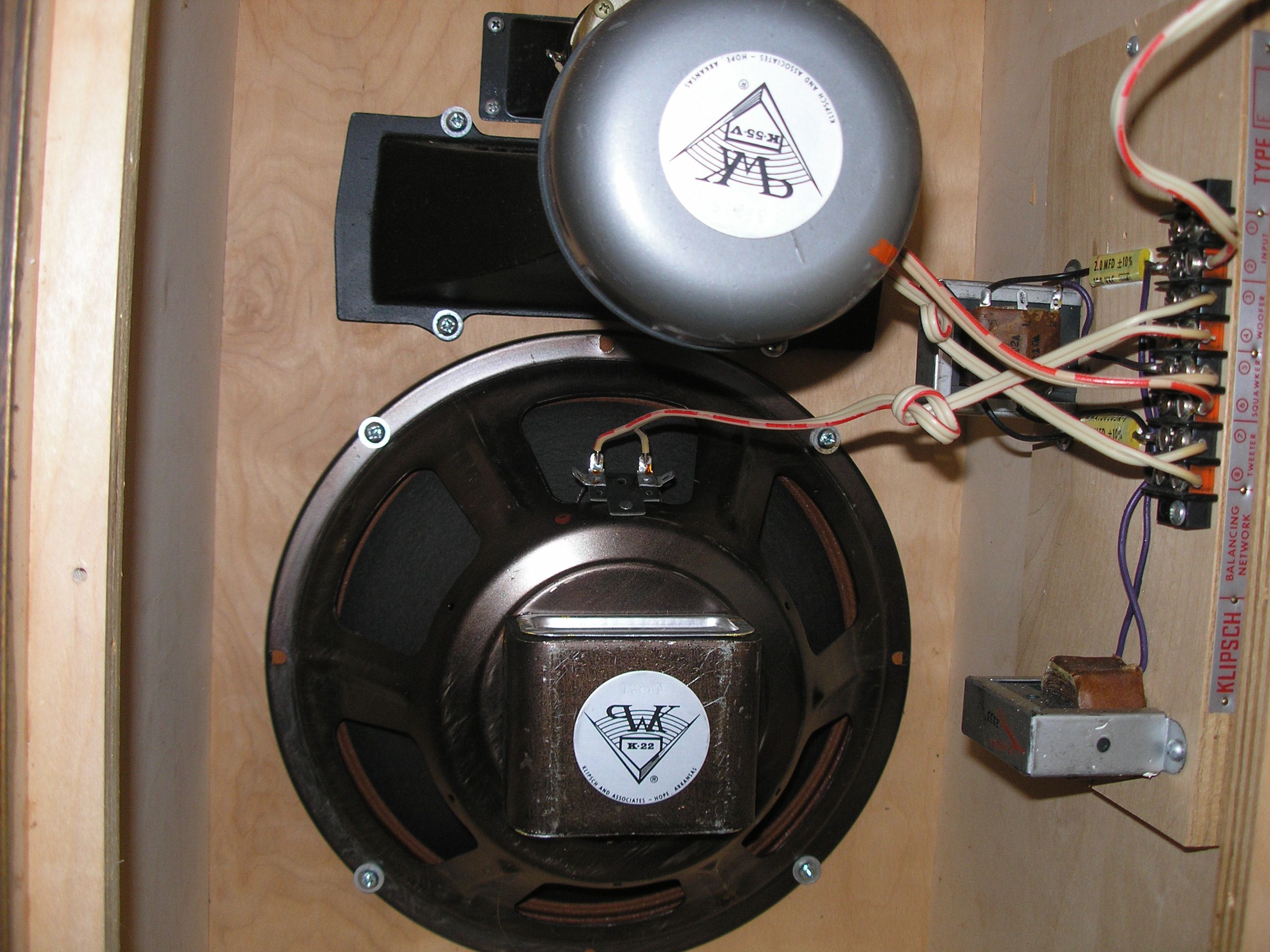
The picture is in fact the correct speakers. I was told when I bought them recently that they had updated networks with JEM caps. Upon closer inspection and comparing them to pictures of JEM caps on the internet, the print on them is different and the JEM kit comes with cable tie fasteners where mine are glued to the board. So my Heresy's have original caps in them, very interesting.
-
Wow thank you for the excellent information. First time for my eyes seeing these stock in older Heritage speakers. They indeed must be pretty rare. You are correct in that all drivers are original Alnico magnets. I prefer the Alnico drivers myself. I can't be 100% certain that my preference is purely sound related, I really like the look of the Alnico magnets and the fact they are lightweight and the speakers are easier to move around. This is due to Alnico having higher max magnetic energy product for the same size compared to Ceramic magnets. Alnico is more stable vs temperature. They can demagnetize but to avoid this they manufacture the magnet in a horseshoe shape, technically that's just what it looks like and it's actually a bar shape. High length to diameter ratios give higher resistance to being demagnetized. On Linkwitz's website there is a "links" page where you can find "putting the science back in loudspeakers". It states; "Using a codec to measure the bit rate of a speaker gives a direct assessment of its figure of merit. The use of this technique has had some further interesting consequences. Traditional loudspeakers use ferrite magnets for economy. However, ferrite is an insulator and so there is nothing to stop the magnetic field moving within the magnet due to the Newtonian reaction to the coil drive force. In magnetic materials the magnetic field can only move by the motion of domain walls and this is a non-linear process. The result in a conductive magnet is flux modulation and Barkhausen noise. The flux modulation and noise make the transfer function of the transducer non-linear and result in intermodulation. The author did not initially believe the results of mathematical estimates of the magnitude of the problem, which showed that ferrite magnets cannot reach the 16-bit resolution of CD. Consequently two designs of tweeter were built, identical except for the magnet. The one with the neodymium magnet has higher resolution, approaching that of an electrostatic transducer. Such precision loudspeakers and drive units require no more than an appropriate degree of rigour during the design stage, along with some high grade circuit design, but have the advantage that there usually needs to be very little change between the prototype and the production phase." Ferrite magnets cannot reach the 16-bit resolution of CD is quite interesting to me. I always thought Alnico sounded better but attributed it to my cognitive bias. I have never been able to do any ABX testing to confirm anything. It's not like switching wires with a test box that can be done extremely fast so memory loss doesn't set in. Even if you had two identical loudspeakers with different versions of the drivers they would have to physically sit next to each other giving them different room interactions making the comparisons invalid. It's tricky to test.
-
Factory "zip" cord in my 1975 Heresy's. Looks like 18awg. For the fella trying to measure his wire gauge with a tape measure that's not accurate enough because you would then need to know insulation thickness to subtract from the total diameter. Your best bet is to strip back the insulation and use a dial caliper to measure diameter and use a conversion chart for stranded wire diameter vs awg. Yes those are the JEM caps installed on the E networks. I have some Russian PIO coming from Bulgaria. All four 2uF caps was $30 which includes shipping. When I have time I'll install the PIO caps on one board and do measurements to compare transfer function, distortion etc..

-
Roger has the most simplest power supply setup. It's a voltage doubler circuit, 700v on the plates and the 350v at the half voltage point for the screens and front end. As for the screen dissipation it's not the 8mA idle current that's a problem, it's when there is signal applied and as the signal gets larger on the plate it swings down close to ground potential. If you have a plate potential at 50v during peak negative cycle the electrons from the cathode will be much more attracted to the screen at 420v vs the plate at 50v. Screen current drastically increases during this portion of the signal cycle.
-
I just wanted to clarify that screen grid ratings are in watts and not current. The old Genelex datasheet says absolute max 8 watts where the design maximum is 6 watts. Which for 420v would be around 19mA for the 8 watts and 14mA for 6 watts. This isn't quiescent (idle) measurements either, when signal is applied and the plate gets pulled down closer to ground the screen grid will have a large increase in current. Try and use a resistor to limit the current, which it will but how it limits current is via a voltage drop which also lowers the screen voltage. This squishes the plate curves together, you can see this via different plate characteristics graphs for different screen grid voltages in datasheets. The less voltage on the screen the more squished the plate curves are, the more voltage on the screen the more the curves open up and separate. This is why regulated screens improve the performance, a simple resistor changes the tube characteristics.
-
La Scala Type AA crossover kit
captainbeefheart replied to bsacco1's topic in Technical/Restorations
DO NOT over torque the screws securing the woofer!!!! You can bend/distort the basket which throws the voice coil out of alignment. People ask all the time why their voice coil rubs and if it's not debris that got in there then it's most likely from a bent/distorted basket, and typically from people not torquing the screws down evenly and too much. -
Some people want a quicker sale and a lower priced item will sell faster. It's a tradeoff in that he gets money in his pocket faster but won't receive top dollar for it. I don't see how you are at any risk. It's not like he is asking for you to send the money order before shipping the item, he just wants a picture to know you bought the money order and not screwing him. When you get the DAC see if it works real quick before mailing the MO out, this seems like the purchase is in your favor because if you are unhappy you can just not send payment and return it. Money orders are very safe. The seller needs to provide an ID when cashing in the Money order so if there is an issue where you get ripped of just tell them the MO serial number and they will either freeze the payment. Or, if he already cashed the MO then the serial number is linked to the ID he used so the authorities have his name. If he uses a fake ID then just about everywhere that cashes MO's will have video monitoring so at least the authorities will have a face shot of the thief. Reasons he might prefer a money order. Doesn't want Paypal to send tax documents to the IRS Doesn't want to pay Paypal the fees regardless if it's out of his pocket or someone else's. If you have to pay the fee then the price isn't as good as it once was. If he pays the fee he gets even less money than what he is asking for. Possible bad past experience with paypal and just hates them and will never use them again. They can randomly freeze your account and tie up your funds. They have been known to hold payment for 21 days for no reason. They say it's a "higher risk" sale but that's BS 99% of the time. Does not have a bank account to transfer his funds to. I personally wouldn't be worried if I were in your shoes. I would ask to speak over the phone and ask the reason for money order. USAudiomart prefers sales through Paypal but money orders, wire transfer, and cash are all acceptable methods. Also do some small talk about hifi gear or music he listens to etc.... Feel out the situation and go from there.
-
Klipsch customer service.
captainbeefheart replied to Chief bonehead's topic in General Klipsch Info
👍 -
Nitpicking Turntable Volume R41PM
captainbeefheart replied to colinsguitaradventures's topic in General Klipsch Info
Ooops my mistake. I looked closer at the picture and it's the back of the powered monitor, the fives have the same exact "line/phono" switch as the Audio Technica TT and so I thought I was looking at the turntable switch. I looked at the fives spec sheet for sensitivity specs but the don't disclose any. I then was curious what his AT cartridge produces for output and it's fairly low for a moving magnet type at 2.5mV output. The "line" option - where if you want to use the built in phono preamplifier on the turntable it only produces 150mV which is quite low for today's line level signal standards. I'd say flip both switches - on the TT and on the powered speaker to "line" and see if you like that better. I'm going to wager that since the TT puts out very low signal for both options it's not going to be much better. They spec the gain of the on board preamp at +38db, with a 2.5mV cart they should have far more gain, closer to +50db but I bet they didn't want to spend time on the design in regard to noise so they just went low gain to get around it. You could always upgrade your cartridge to something that puts out 5-6mV, some output 8-10mV and you'll get a lot more volume from phono setup. Again sorry for the confusion. -
Nitpicking Turntable Volume R41PM
captainbeefheart replied to colinsguitaradventures's topic in General Klipsch Info
He has the switch on his TT wrongly set to "phono", it should be set to "line". It's not a selector switch where you are selecting to listen to "phono". Instead it's asking you what you are plugging the TT into - a line stage or an actual phono stage? If you have the switch set to "phono" it thinks you are going into a preamp with enough gain and with the correct RIAA EQ and so takes the signal directly from the cartridge. Conversely if you have the switch set to "line" then it thinks you are connected to a preamp line stage input and so it sends the signal from the cartridge through it's own local on board amplification stage of +38db and the proper RIAA EQ. So it's no surprise that with the switch set to "phono" and plugged directly into an active speaker system intended for line stage signals that the output will both be very low due to insufficient gain, but also sound awful because the RIAA frequency correction network isn't present. -
1962-1983 Letter format A=62 F=67 K=72 R=77 X=82 B=63 G=68 L=73 S=78 Y=83 C=64 H=69 M=74 T=79 D=65 I=70 N=75 U=80 E=66 J=71 P=76 W=81
-
That's just "California" prices. 🤣 They just passed a "speaker sales tax" to fight "sound pollution". 🙂
-
Wow those are gorgeous!! You are smart to do this before the move. We downsized to a ranch a recently and I just didn't want to let go of my La Scala's so we moved them up to the new house. I'm going to sell them now because in my new smaller listening room they just didn't have the magic they had in the larger room at the old house. I swapped them out for a pair of 1975 Heresy's and the smaller speaker works in conjunction with the room so much better. The imaging came back and I can get that allusive phantom auditory scene back again. I'm actually findng I'm not turning my subwoofer on at all anymore unless I'm really in the mood to shake the house which doesn't happen as frequently as it did in my younger days. I'm still working on room treatment, aiming for time delays of around 450mS so the room is neither "dead" nor overly "live". It's good enough for now as my toes tap and my mouth does this weird smile thing. GLWS!!!!
-
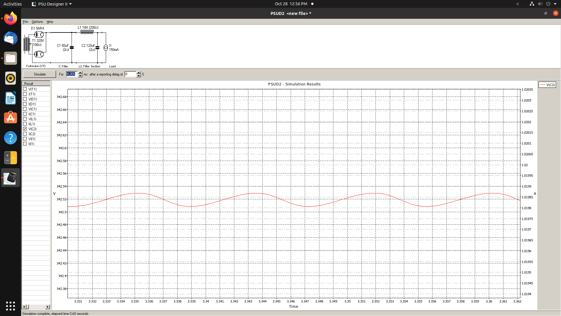
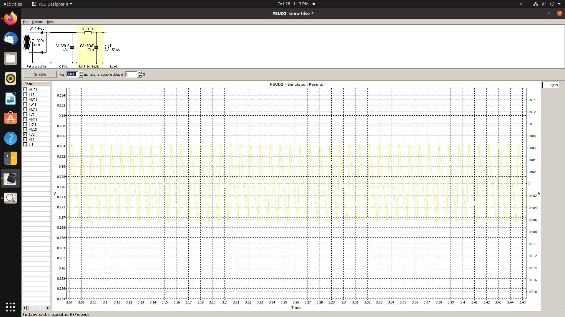
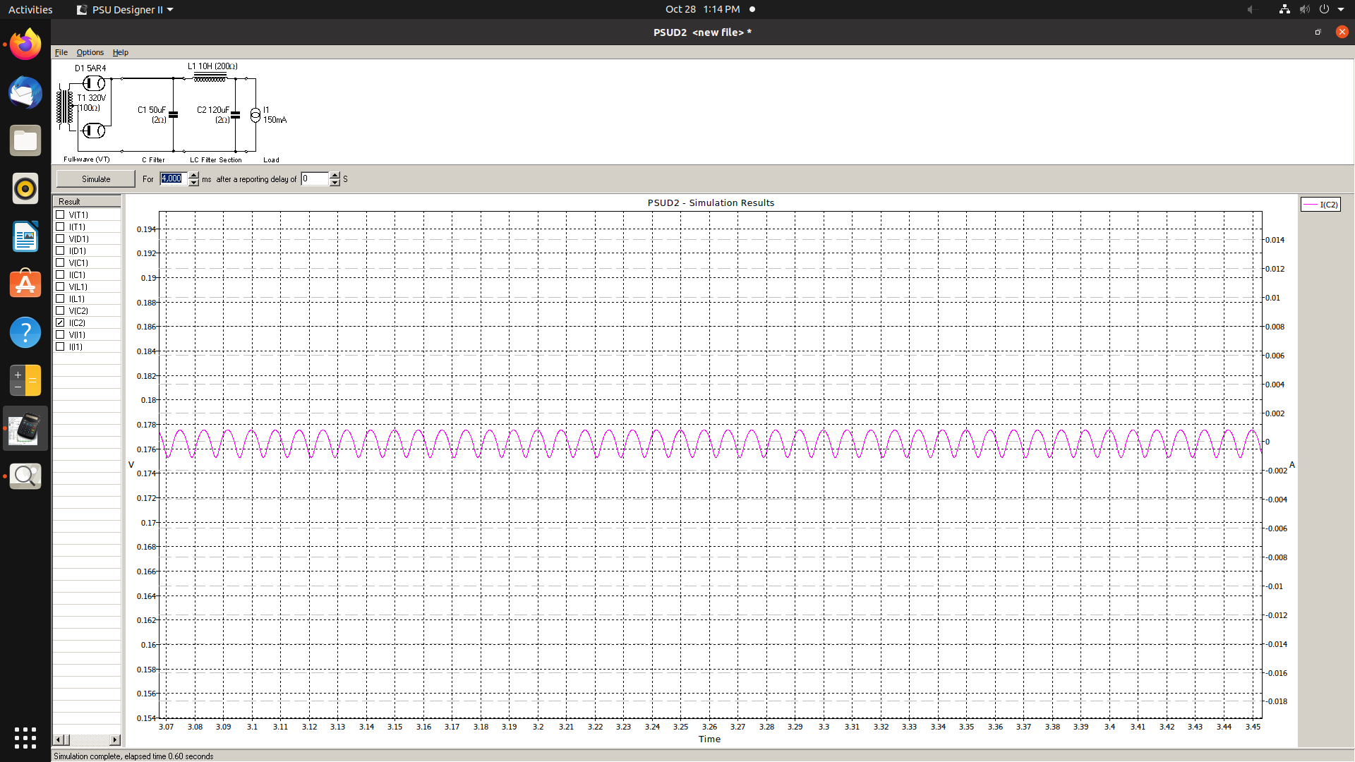
Here are two simulations between the two. One is SS rectified with large value capacitors. The other is tube rectified with a choke. I had to increase the voltage of the secondary winding to make the comparison more accurate for the same output voltage of 340v. The 5AR4 is within it's peak repetitive forward current rating and peak surge current rating. The SS rectifier circuit has double the ripple compared to the tube rectifier circuit. What I really like about chokes and tube rectifiers is capacitor life is extended for all filter capacitors after the choke. Along with the plots for ripple voltage at C2 I'm also posting the ripple current through C2. Yellow is the SS ripple current through C2 and the blue is tube+choke ripple current through C2. Have a look at the ugly and large current waveform. C2 will certainly have a shorter service life in the SS no choke circuit compared to the tube rectifier and choke circuit. Electrolytic capacitor life is determined by heat and the current passing through it. Another bonus I like about tube rectifiers is I don't need to work out a snubber for rectifier induced ringing which doesn't typically occur with tube rectifiers but almost always does with SS rectifiers. Yes chokes and tube rectifiers are more expensive and take up more space. But if we are after efficiency then we might as well just ditch tubes all together and go Class D.
-
Let's stay on topic since this is a great conversation and I'm sure there are lots of lurkers interested in this topic and following the discussion. So moving forward Some say ditch the tube rectifier and use SS so you can use larger filter caps and not need a choke. With SE amps and no common mode rejection at the output stage I think if you are going to want good performance a choke is necessary and you won't get as good ripple reduction with just larger caps in RC networks. Well unless it's a flea watt amp then there might be low enough current to not need a choke. For the uninitiated it's the capacitor directly after the rectifier that needs to be lowered with a tube rectifier, not so much the capacitance further down the power supply networks. Let's assume a single ended Class A amplifier 2 channel amplifier. Total DC load current of 150mA. Typically minimum I feel for each filter stage is at least -20db but the lower the better obviously. With -20db we need each filter stage to have 1/10 impedance ratio; i.e. the resistor needs to be at least 10x the impedance of the capacitor at 120Hz. For a full wave rectifier we need to filter 120Hz. There isn't much of a point going higher than 470uF because it's impedance is around 2 ohms. In the divider network of the filter going any lower in impedance has more and more diminished returns. With 150mA you are most likely going to be maxed out at around 150 ohms for the resistor value. That gives us around 22v drop across it and over 3 watts dissipation. But since this is just hypothetical let's go crazy and make the series resistor 330 ohms. With 150mA that's a 50v drop and 7.5 watts of dissipation!!! You'll most likely want a minimum of 20 watt resistor rating. Big and hot!! With the 470uF cap the 330 ohm resistor we get roughly -44db ripple attenuation. Now with a 10H choke - which is 7.5k impedance to 120Hz. And we will use a 100uF cap. This filter roughly gets us -55db. In many builds I'm below the repetitive peak forward current with 100uF after the choke and can safely use used 220uF in the past. This will get you down to -62db. Not too bad considering a SS rectifier with the choke and 470uF you would be at -71db. -62db vs -44db, the choke more than makes up for the slightly reduced ripple you would get from a larger value reservoir cap and SS rectification. If you are going to build single ended amps with more than flea power a choke is pretty much necessary if you want the best performance. And if you are going with LC filters than you might as well add the cool factor of a tube rectifier since it's not going to make a difference in performance going SS.
-
⚡
-
The RCA 50 watt amplifier uses a 5R4 rectifier which has lots of sag if used with a C input filter. Looking at the schematic you'll see it's a choke input filter. The screens are regulated. Local and global feedback loops. I made a pair of mono amps with this circuit except I swapped the 7199 for 6BL8 and I used 6L6GC for the finals. This amp has amazing performance. Although it uses the lossy 5R4 rectifier it's of no issue due to the choke input filter, the regulation is stiff under full power. I was getting 50 watts output with .07% THD. That's pretty darn impressive if you ask me. This design blows many of the more popular cloned circuits out of the water. I am always curious to why more people do not clone this circuit more often since it's so impressive. I know the golden ears don't care about "specs" like low distortion but the amplifier sounds better than McIntosh amps, at least I think so. I compare against McIntosh because they too have very clean and powerful amplifier designs.