babadono
-
Posts
10184 -
Joined
-
Last visited
-
Days Won
6
Content Type
Forums
Events
Gallery
Everything posted by babadono
-
General Technical Question RE: RCA input on amplifier
babadono replied to beerguy's topic in Solid State
Correct. But things are changing...many IsoMax models are unobtanium...I suspect certain transformers will go by the wayside also....just my opinion/belief. But I am an idiot. -
Smoking dope in front of the cops then getting behind the wheel to drive off? Why'd ya think they call it dope. WPOD....white punks on dope....
-
WHAT!?
-
Is that a "polyswitch"? .....calling @Deang
-
Wow...looks like that absorbed some energy. Is the tweeter still OK? Are the traces on circuit board still intact?
-
yes you will have to 'resize' them to be under the 2 Meg limit. I use an email program to squeeze them and send to myself. Then I can copy and paste wherever needed.
-
This commercially available product claims to do what you need: https://russound.com/products/audio-systems/multi-room-controllers/expansion-devices/adp-1-2-speaker-to-line-level-adapter#product_images it is basically a voltage divider. It has such high values of resistance that it will not change the load seen by your amp. You will then have to use the Low Pass control on the sub to limit the frequencies to the sub. And the volume control of course. Personally I would just build my own, but that's just me.
-
Can you say voltage divider? I am going to guess at 10k input impedance(cannot find a spec) so try 100k in series with the input.
-
General Technical Question RE: RCA input on amplifier
babadono replied to beerguy's topic in Solid State
Jensen is now owned by Radial Engineering out of Canada...not making any predictions but I would procure what you want/need ASAP. @Marvel you saw this comment/observation? -
BTW most 'experts' recommend diffusion on the rear wall as opposed to absorption.
-
and don't forget the floor and CEILING.
-
What about the first reflection point? Stop that first bounce.
-
Hmmmmm...mighty tempting...
-
What?👂 Merry Christmas to one and all
-
Are these the mini-me horns that @ClaudeJ1 used to rave about?
-
General Technical Question RE: RCA input on amplifier
babadono replied to beerguy's topic in Solid State
Yes Sir -
General Technical Question RE: RCA input on amplifier
babadono replied to beerguy's topic in Solid State
Here they are:
-
General Technical Question RE: RCA input on amplifier
babadono replied to beerguy's topic in Solid State
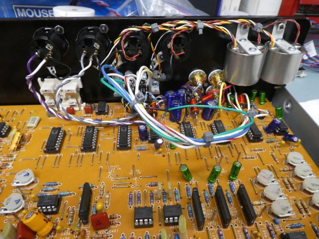
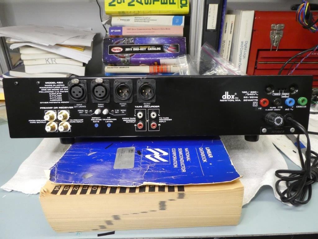
is this close enough? https://www.mouser.com/ProductDetail/Switchcraft/PJRAS1X2S02AUX?qs=mcPJWgAPNrf54bk5GcnDZQ%3D%3D&mgh=1&gad_source=1&gclid=EAIaIQobChMIjL-_i4-hgwMVXi-tBh0AIwGHEAQYBiABEgJGXPD_BwE Personally I would get rid of the PCB mount type. Get a standard panel mount type and add an inch of wire. It is the force transferred on the connector down to the PCB that breaks connections and cracks traces on circuit boards On the right the standard PCB mount jacks have been replaced with standard panel mount type. This is the main in and out connections. On the left are the PCB type that is the tape monitor loop connection which I left as is because I don't use. WHY DONT THIS CHEEZEBALL APP ALLOW ME TO ATTACH PICTURES -
Fixed it fer ya.
-
Getting the La Scala Band back together - on a Budget
babadono replied to ShoreMedic's topic in 2-Channel Home Audio
Cotf? -
$4000 for a 10 watt amp...does it really sound THAT good? Too rich for my blood, I won't be able to discern the difference.
-
General Technical Question RE: RCA input on amplifier
babadono replied to beerguy's topic in Solid State
RCA input jacks are unbalanced input connections. Yes the shield needs to go to the chassis on the left input just like the right. If it has always been like this you have been lucky. Or perhaps a solder joint has cracked or opened in some other fashion. Could even be lifted foil on the circuit board. What amp is it? Everything you wanted (or didn't) to know about grounding: https://centralindianaaes.files.wordpress.com/2012/09/indy-aes-2012-seminar-w-notes-v1-0.pdf -
is OP @johnq saying he has his current receiver turned all the way up and he would like to be able to turn it up more?
-
DMH....Sent you a PM attached to an old PM...hope you get it. If you don't respond I'll send a new PM.
-
doing it is allowed I mean who gonna stop ya the Speaker Police? But posting about it is not.