
John Warren
-
Posts
2263 -
Joined
-
Last visited
-
Days Won
1
Content Type
Forums
Events
Gallery
Everything posted by John Warren
-
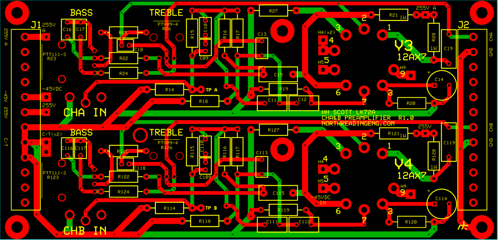
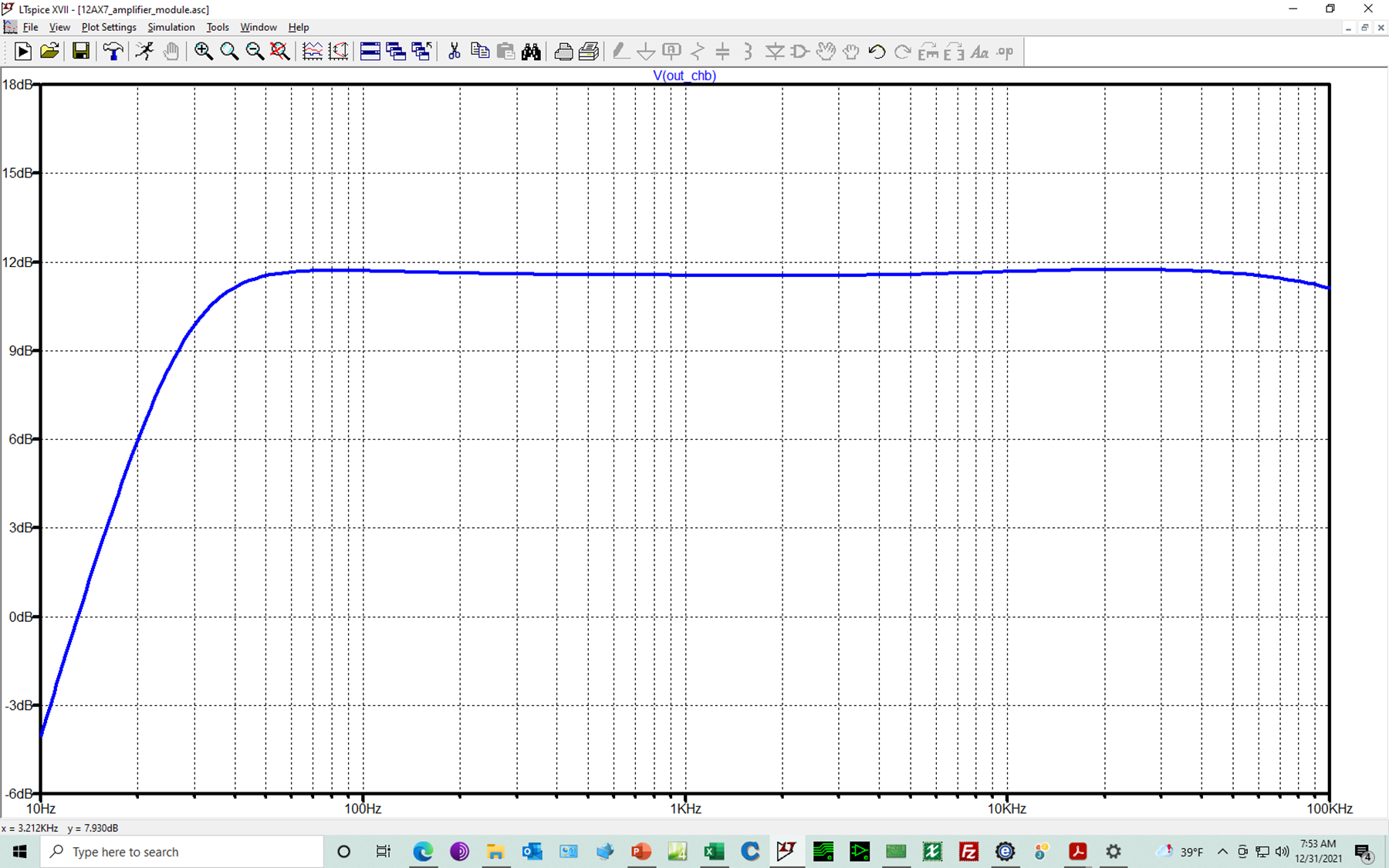
Let's break out a 12AX7 preamp board from the LK72 schematic. I managed to squeeze both channels including bass and treble potentiometers on a 2-layer, 6.6x3.18" board (the max size allowable before incurring a much higher fabrication cost). Requires two inputs: 255VDC (anode) and -45VDC for filament heaters. Simulated bandwidth using LTSPICE. Input will be adjusted using external audio taper potentiometer.

-
Replacing k55v with a55g(1st gen) LS w/AA xover
John Warren replied to Alexander's topic in Technical/Restorations
What's an A55G? -
Recommendations for a tube amp tech in Arkansas or close by?
John Warren replied to avguytx's topic in Talkin' Tubes
How to rate your service tech? A wee test: Capable of working amps others have butchered, including those with highly regarded reputations. Has spectrum, distortion analyzers and other expensive, well maintained analytical instruments everywhere. Manages 20 pounds of unusable, trash shipping materials for each amp received Enjoys spending endless hours figuring how to pack each amp and get it shipped so the carriers can damage it. Maintains vast inventory of difficult, hard to find electronic parts Has a source for free, low production rate transistors sourced from factory authorize distributors Buys nothing from NTE Sees one-of-a-kind factory designed parts that break when touched a "challenge" Has a source for free shipping materials such as cartons, packing foam, tape Highly skilled, former McIntosh certified repair tech Somehow possesses a viable business model with shop labor rate $8/h -
Here's the schematic I used. XLi1500 120V Schematic.pdf
-
Did the factory offer cabinets with edge exposed plywood? Top sections look DIY. Does the badge shown in the photo jive with 1988?
-
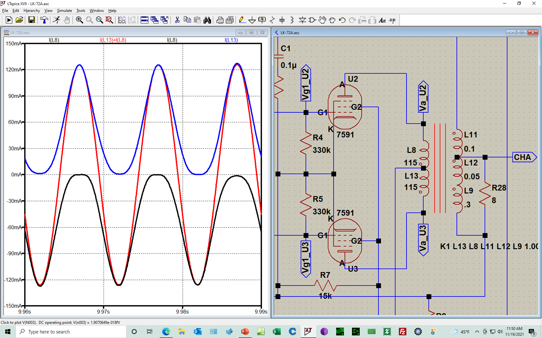
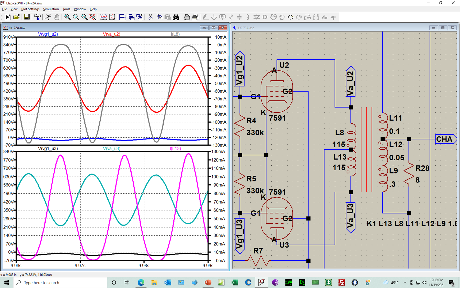
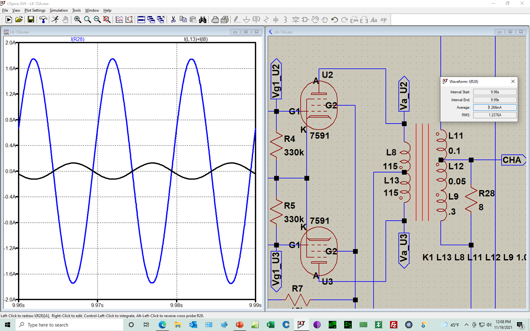
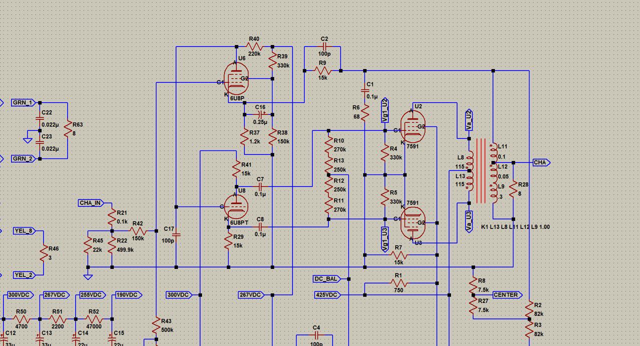
Plot at left show current flow in bottom half of output tube primary (blue trace, I(L13)) and black trace top half I(L8). Summation is red trace (I(L13) + I(L8). Same current plots as above but with addition of grid and anode voltages for each pentod3 (U2 is plotted top, U3 bottom) Blue plot is current trace on secondary running thru 8 Ohm resistor (1.2A RMS), black is current in primary (89mA RMS). Secondary current is ~13.5x wrt to primary.
-
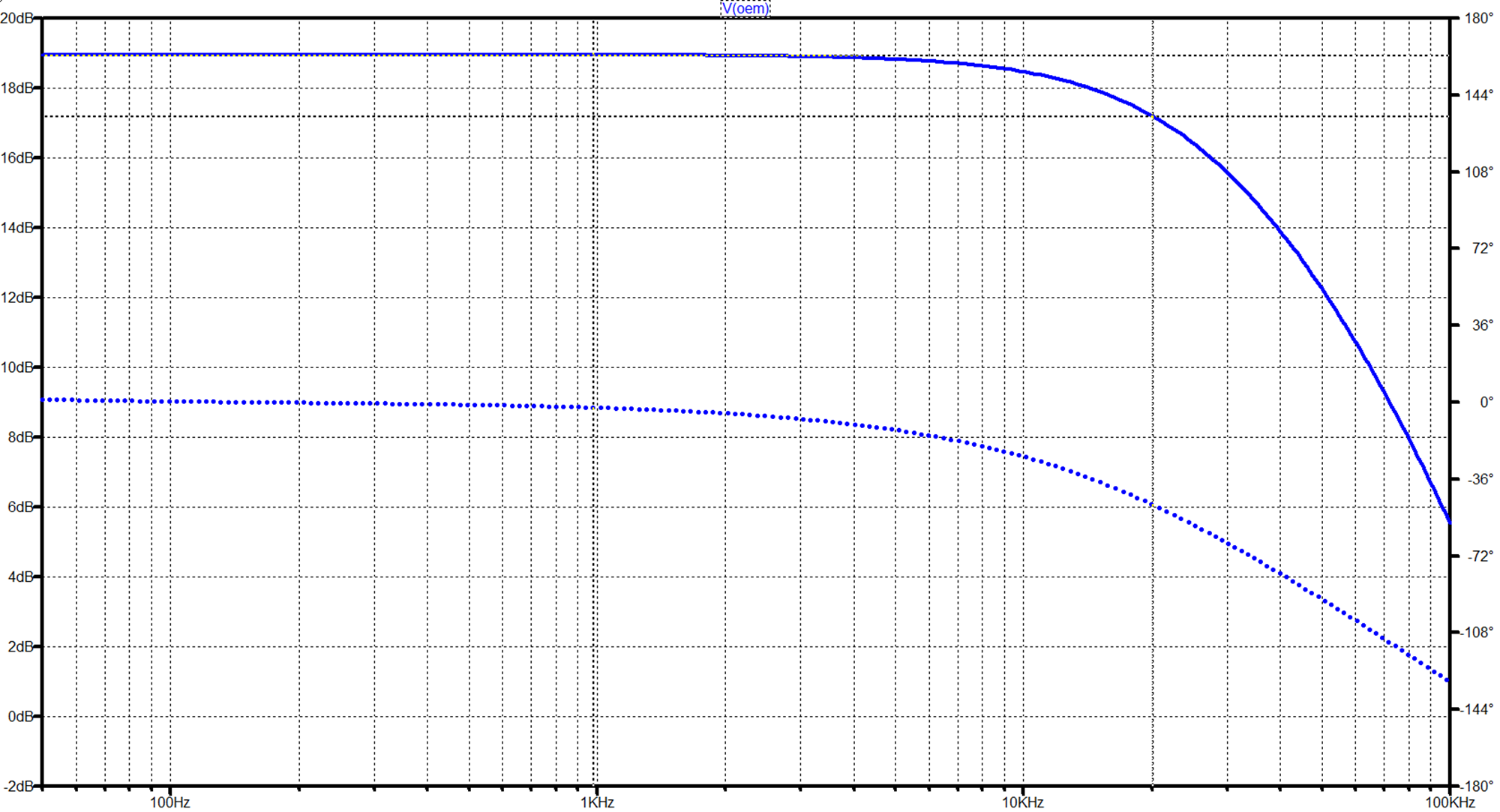
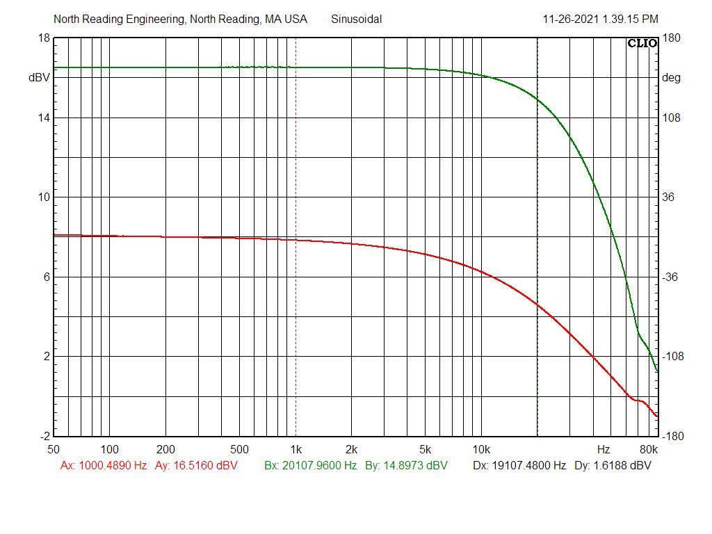
The plot below is a simulation of the Scott clone 299C bandwidth and phase to 100kHz. The schematic is shown above but a few of the values shown there have been revised to better approximate the amplifier configuration tested. The Hammond 1650PA, 6600 Ohm input impedance output transformer is modeled based on the specifications provided by Hammond (input impedance, DCR each winding, primary inductance and leakage). Below is measured response of the amplifier. Reasonable prediction of the result.
-
The plots I posted were for another circuit, not the Scott. My apologies!
-
I purchased the scope when I was 29 years old from the on-site Tektronix FS engineer while I was working at Raytheon Microwave Power Tube Laboratory (Waltham, MA). That was in 1987!. Also, it's a 465 but from the photo could be a 475.
-
wrong amp
-
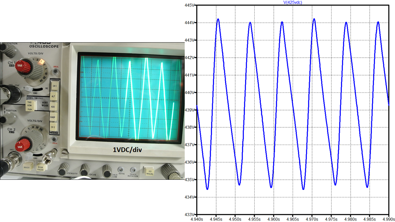
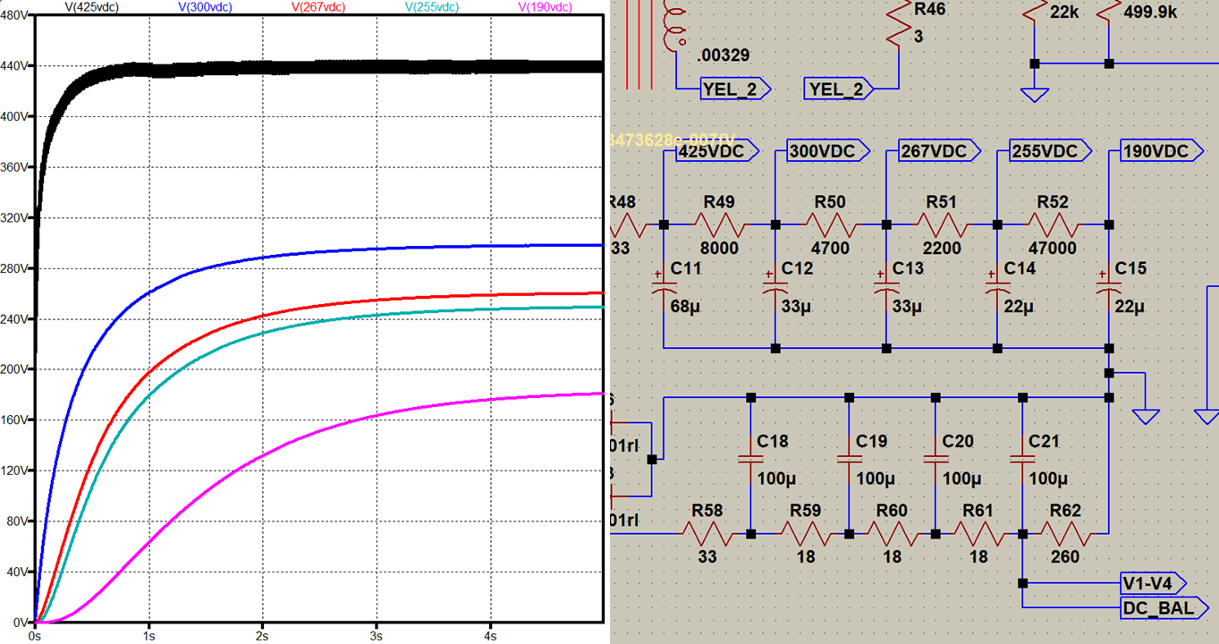
425VDC center tap out sim v. measured.
-
DC rails
-
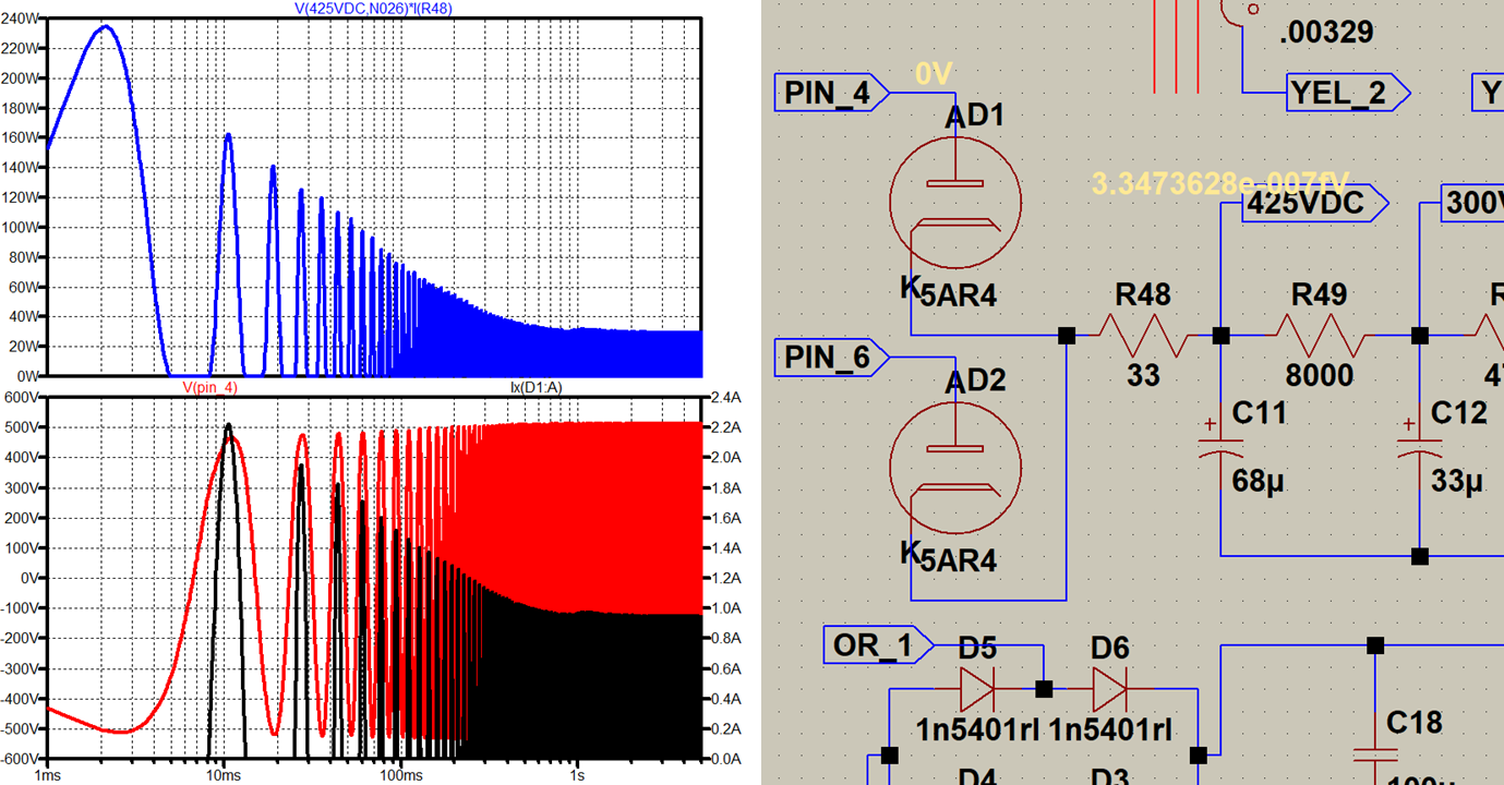
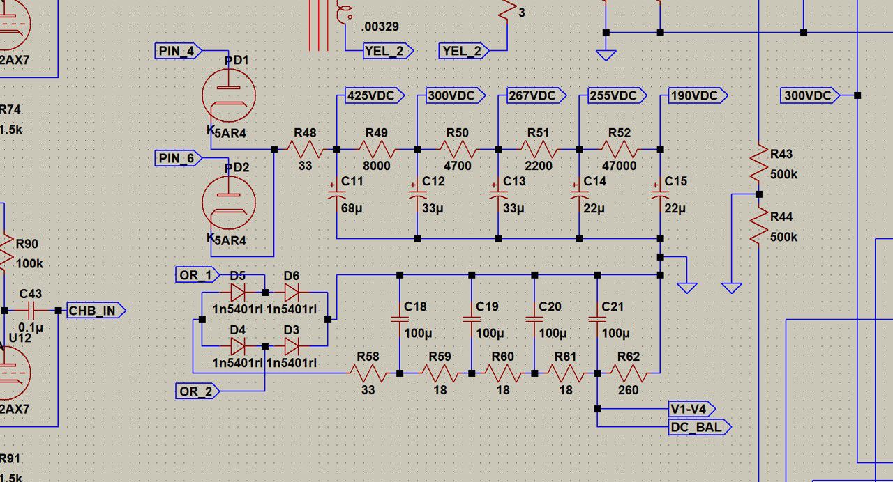
Plots show rectifier tube turn on current thru D1 side of 5AR4 (black) and voltage at Pin 4 (red). Blue is power dissipated by R48 which, at steady state at about 5 seconds, is ~12WRMS.
-
I didn't bother modeling the AC entry module EMI/RFI filter I installed on the unit I built. Transformer coupling coefficients are set at 1.00 but are generally lower. Transformer resistances are measured immediately after shutdown while still hot. Capacitors are modeled with series and parallel parasitic elements (Rser, Lser, Rpar, Cpar, RLshunt) Filaments are modelled as pure resistances Wall power is perfect, 60Hz sinusoidal although noise and HF artifacts can be added. Rectifier tube 5AR4 has parameters in the tube sim that simulate rail sag (not easy but did it!). Speaker load is 8 ohm non-inductive resistor but reactive loads can be simulated easily.
-
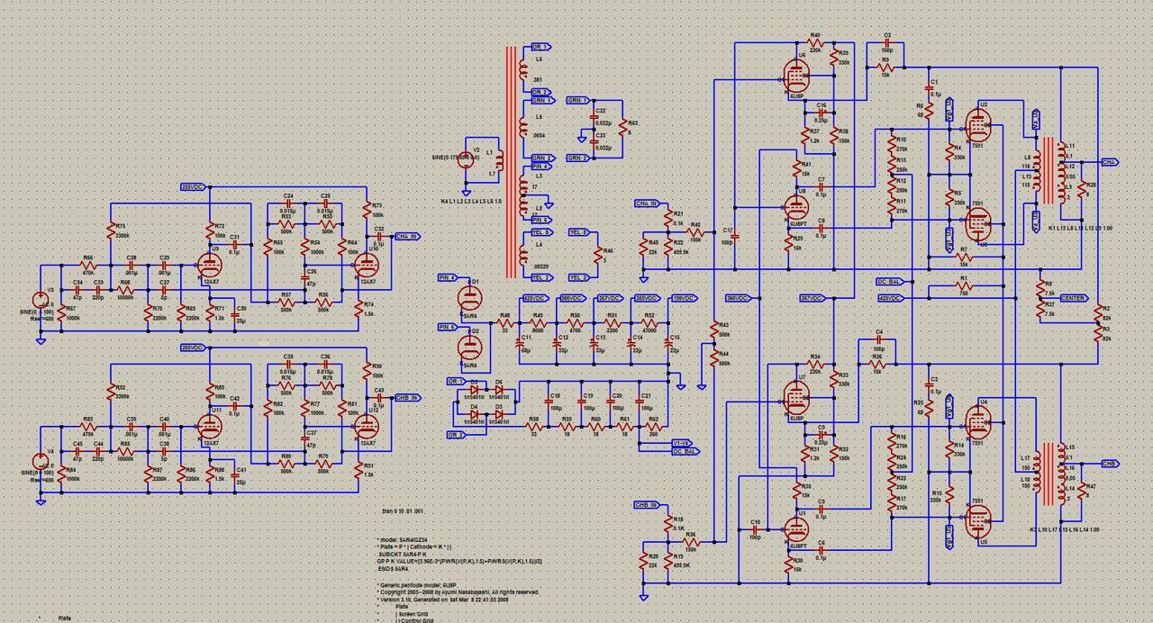
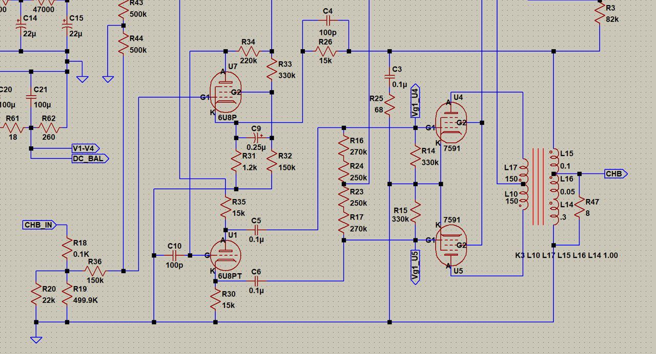
Here's a model the Scott LK72 (minus the phono pre), thought some here would be interested. The tube models are both my own and a few found on the web. I'll first post a few screenshots of the schematic and the run a few sims to show what's possible. Some advantages of running a simulation before committing to hardware: Determine dissipation power of components, find hot spots and size accordingly View current waveforms Peak-to-peak voltages Bandwidth, instability analysis and compensation Output transformer loading Predicted behavior with reactive speaker loads Overall model: Power supply transformer: Power supply: Channel A: Channel B:
-
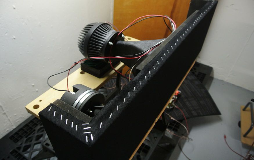
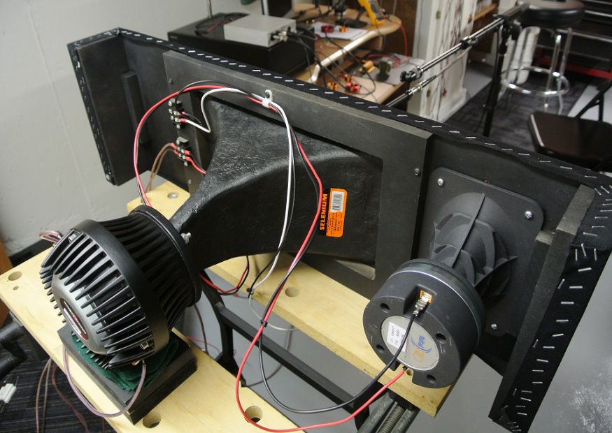
ZXPC 18" x 10" Two Inch Format Horn
John Warren replied to Curious_George's topic in Technical/Restorations
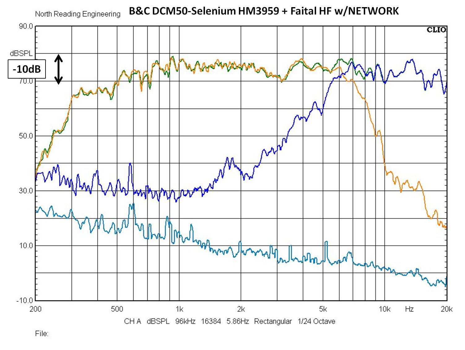
I spent time with this combination Faital and B&C drivers for Klipschorn. The net was a bit complicated but overall, the sound was quite good and blew away the stock hardware, not even close. The frame was designed to slip into the top of the Klipschorn
-
use it as a center channel amp
-
Maron's wife, through an friend of hers, contacted me after his death. She had a long Excel list of hardware he owned. It's not clear to me how she came across my contact info. He either instructed her to contact me or found my contact information in his personal papers. Either way, she asked me to evaluate the list and estimate sale prices so she could sell it without getting short changed. She didn't want to deal with buyers directly and I didn't want to take the task on of being a middle man. I thought about buying the whole lot but I'm past the point of collecting vintage hardware. There were many JBL vintage pieces.
-
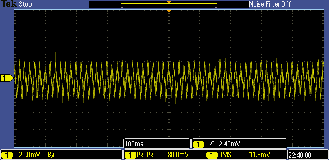
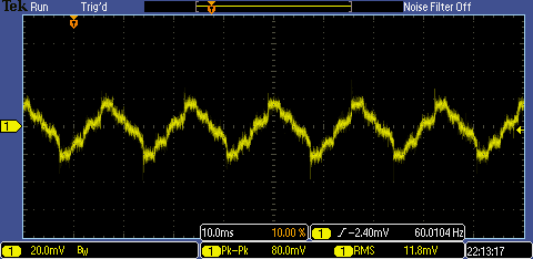
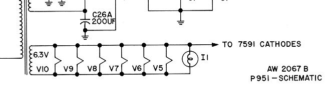
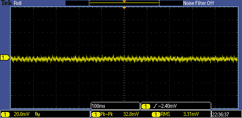
I've been asked about tube amp hum/buzz and how to get rid of it. It's noticeable buzz when the amp gets to heat and doesn't change when the volume pots are adjusted, it's just there. This is what it looks like on an oscilloscope, at 20mV/division. The amp is idling and the load is an 8 Ohm power resistor. The scope probe is across the resistor over a 100ms time window. Below is with the time window reduced to 10ms. It's not a sinewave, it's a 60Hz sawtooth. And with a peak to peak amplitude of 40mW, ignoring high frequency glitches, it's audible especially when you're speakers have high sensitivity tweeters. The 6.3VAC heater secondary tap is prone to picking up wave characteristic (periodic) noise from rectification, line voltage and other sources. The noise is coupled to the tube cathodes. Heater supplies configured below (a Fisher design) are problematic. There's a few ways to improve the situation (see artificial center-tap, Humdinger potentiometer). There's other approaches but these are common. Here I use the artificial center tap concept but replace the "typical" 100 Ohm, 2W resistors with .022uF, 400VAC Orange Drops thus filtering the rails of periodic harmonic garbage and the result (before and after) is below. RMS value of noise is reduced three-fold and, most important, the amp is silent even when the ear is against the grille cloth. Note that the peak to peak readings report glitches which are momentary impulses that are of no significance. So why did the engineers at Fisher, Scott, Pilot and a few others not add a couple of resistors or capacitors to their designs? I would propose that the hum, though noticeable with no program material is of such low magnitude that it made little difference to the sound quality.
-
The 25W rating is the power dissipation the windings are designed for.
-
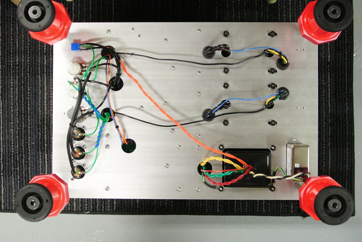
Nothing exciting. I've had inquires to purchase either as a completed unit or a kit. I purchased parts for three units and the third is built but waiting on the 7591s and, as of today, JJ is still down due to material shortages. I ordered the tubes early June. Regardless, I've ordered more hardware to a make a few more amps. The chassis plates will have mounting hole patterns to accept either the Lundahl, Hammond, Transcendar or OEM output transformers. The Lundahl OTs are heavy and the housing, which is nice btw, has four threaded holes for M4 screws at the bottom for mounting to a chassis. M4s are too small. If I was to ship amps with M4 screws holding the transformers down they'd likely break the screws. That said, the next sets of performance tests I'll show will be with the Lundahl output transformers. Here's the wiring on the underside of the chassis (unit #3).
-
EV published the DIY plans for the Georgian and sold drivers for the enclosure. The woofer should be a 15W K, the K is stamped into the rear badge for Klipsch. The DC resistance is 3.1-3.3Ohms. The issue with these old drivers is the voice coils are fragile and can't take much heat. They're tube era drivers. The Georgian was EV's version of the Klipschorn which they licensed from Klipsch to produce.
-
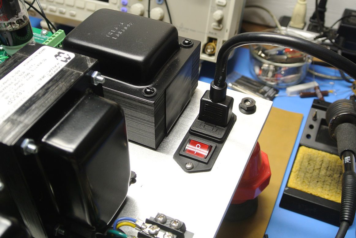
And you can install a 1A fast or slow blow fuse in the Variac to limit current draw regardless of what the Amp meter shows. Regarding the amp meter, I use a Fluke that measures in mA AC. Most tube amps idle at about 1000-2000mA. I have a dedicated VAC meter on the setup as well.
-
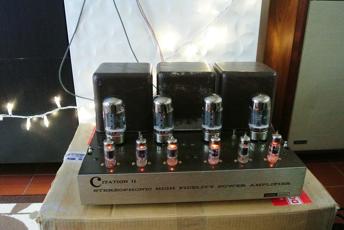
I purchased a Citation II. The important bits and pieces are there and it sounds good but it needs a good going thru. The chassis is in good shape and the transformers are fine. Every other piece, including the boards will be replaced. I'll restore the entire thing to museum quality and when I die leave it to one of my kids.
- 881 replies
-
- 10
-

-