mboxler
-
Posts
574 -
Joined
-
Last visited
Content Type
Forums
Events
Gallery
Everything posted by mboxler
-
Interpreting These Crossover Measurements - ALK Universal
mboxler replied to naaac's topic in Technical/Restorations
What value inductor are you using for the woofer? Looks like you would need a 6.4mh to cross a 16 ohm woofer at 400hz. -
The more I look at the picture, this may be easiest (and what you were suggesting). Is there enough of pin 5 exposed to allow a quick disconnect to push onto? If so, remove the wires you marked red from the input. Maybe wrap the spade with electrical tape to make sure it doesn't make contact with anything. Crimp a spade connect to one end of the wire and a quick disconnect to the other end. Connect to spade end of the wire to the input red. Push the quick disconnect onto pin 5. I think that should work. Mike
-
Sorry for the late reply @Gints. Yes, that sounds correct, but if you want to modify the current crossover, I think this would be easier... Leave the 2.5mh inductor. Since the woofer will not be connected, no current will pass through it anyway. You can leave the 6.8uf cap in place IF you can run a wire from INPUT to pin 5 of the autoformer. This wire would be in parallel with the 6.8uF capacitor, causing very little current to pass thru the capacitor, like it's not even there. With this setup, the 3db attenuation would not be needed in the miniDSP. If you don't like the results, remove the wire, and you're right back to where you started. There shouldn't be any load issues. If you want a greater and more consistent load on the high pass amp, you could solder a 10 ohm resistor from pin 0 to pin 5. But I'd take it one step at a time. I always place an 8 ohm resistor across the tweeter output, a 13 ohm resistor across the mid output, and use a cheap amplifier to pass varying frequencies to the crossover input. Using a true RMS multimeter, I measure the voltages across everything just to be sure I didn't screw something up, then connect to the drivers. If you lived in the Denver area I'd be happy to help you with this. Hope all this makes sense! Mike
-
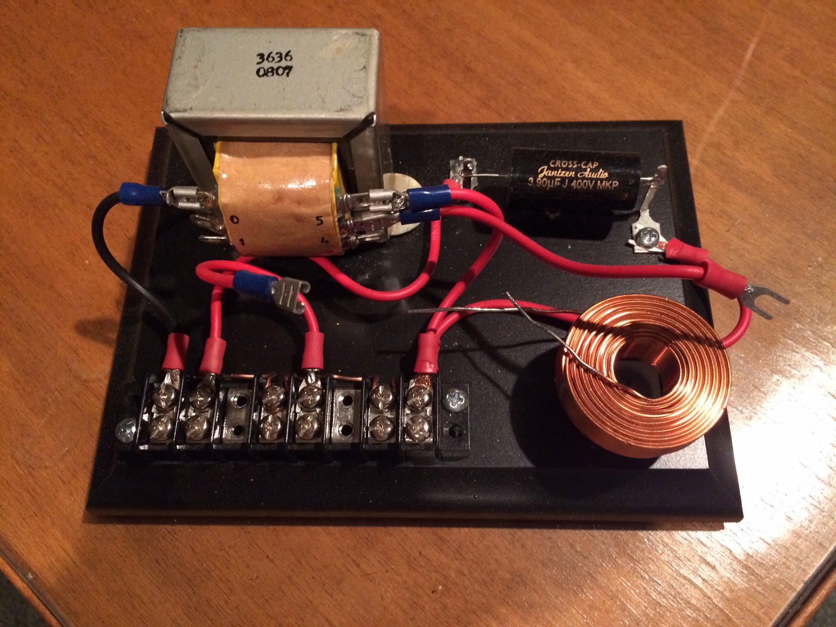
Not sure how your DIY skills are, but the resulting circuit is quite simple... Autoformer 500uH inductor 4uF capacitor Here's an unfinished AB-4500 (type A, bi-amp, 4500hz) crossover just to give you an idea. I believe for your CS you would attenuate the hi-pass output of the miniDSP by 3db. The nice thing about this setup is you can attenuate the PD-5VH to match your CT-125, then attenuate the high pass output from the miniDSP to match the low pass to the woofer. Mike

-
Reminded me of this video... https://www.youtube.com/watch?v=MBRqu0YOH14 I realize this is 6 minutes of your life that you will never get back.
-
Streaming better sounding than hi-end CD ??
mboxler replied to richieb's topic in 2-Channel Home Audio
Radio Paradise just released their lossless web player. And for any of you using MIchael Herger's Squeezebox server and Radio Paradise plugin, he just updated the plugin to allow access to the four FLAC mixes. Mike -
T9A AUTOTRANSFORMER HOOKUP QUESTION.
mboxler replied to longdrive03's topic in Technical/Restorations
The T9A actually has -3db attenuation. The T4A has -4db attenuation. Looks like the T4A was used in the Belle AB-2 crossover. If using the T9A... Hook input - to 0 output - to 0. Hook input + to 5, output + to 4. Mike -
Since the woofer is getting all frequencies, his crossover looks like a first order band pass to the autoformer/squawker and a third order high pass to the tweeter.
-
There should have been a 4mh inductor and two 70uf capacitors in the bass bin. If you removed them, and have only wire between the input and the woofer driver, than yes the woofer is receiving all frequencies.
-
Not sure if you want to know what the current rating of the stock 2.5mh inductor is, or how much current can pass through the inductor. I don't know the stock inductor rating, but... I believe the K-33 can handle 150 watts. If we assume the lowest impedance is 4 ohms, and use Ohm's Law, that equates to around 24 volts and 6.1 amps. Since the inductor is in series with the K-33, current through both will be the same...6.1 amps. Perhaps over simplified, but I hope that helps. Mike
-
Oddly enough, I'm currently "rebuilding" my ALK Universal kits I purchased quite a few years back for my K-horns. It was my first soldering project, and it looked like gray gum wadded around the connections. I'm seriously considering replacing the 1.3mh woofer coil that came with the kit with the 2.5mh value used in the type A and AA. I know Al argued for the 1.3mh, but I find it odd that his Super AA upgrade keeps the stock 2.5mh woofer coil. While testing the rebuilt crossovers, I wanted to find out the frequency where the voltage across the 1.3mh inductor equals the voltage across the K-33 (the -3b voltage point). It turned out to be around 1400 hz! As it turns out, the impedance of a 1.3mh inductor at 1400 hz is 11.4 ohms, which must be the impedance K-33 at 1400 hz??? For fun, I hooked up a 2.5mh inductor between the amp and the K-33, and found the -3db voltage to be closer to 400 hz, or 6.2 ohms. Seems like replacing the ALK Universal woofer coil might be an interesting experiment. Mike
-
Using this calculator http://www.pronine.ca/capimp.htm Change Capacitance to uF and Frequency to Hz. A first order rolloff (-3 db) occurs when the impedance of the capacitor equals to impedance of the series load. This occurs at a specific frequency. The tweeter capacitor ALWAYS has a 8 ohm load (the K-77). Using the calculator, plug in 2 uF and 8 ohms. When you click Calculate, the Frequency will show 9947.1875 Hz. That's the crossover frequency to the tweeter. Moving the tweeter tap will not change this, because the cap is after the autoformer. The K-55 cap (4 uF) is before the autoformer. Since it is using input 0-5 and output 0-3, the impedance of the K-55 appears 4 times bigger. Assuming the impedance of the K-55 is 15 ohms, the load on the 4 uF capacitor will be 60 ohms. Plug those numbers into the calculator, and you will get a frequency of around 663 Hz. If you change the output tap to 0-2, then the load is 8 times bigger, or 120 ohms. If you want to keep the same 663 Hz crossover frequency, plug in 120 Ohm, 663 Hz Frequency, and the calculator will determine that a 2 uF capacitor is required. Hope that helps! Mike
-
Interesting. Are you running a 400 hz low pass signal from the Xilica XP 4080 straight to the K-33, but a delayed full signal from the Xilica XP 4080 to the HP section of the original crossover? The 13 uf capacitor of the HP crossover is still the high pass filter for the K-55? Mike
-
What passive are you using for the mid to high crossover?
-
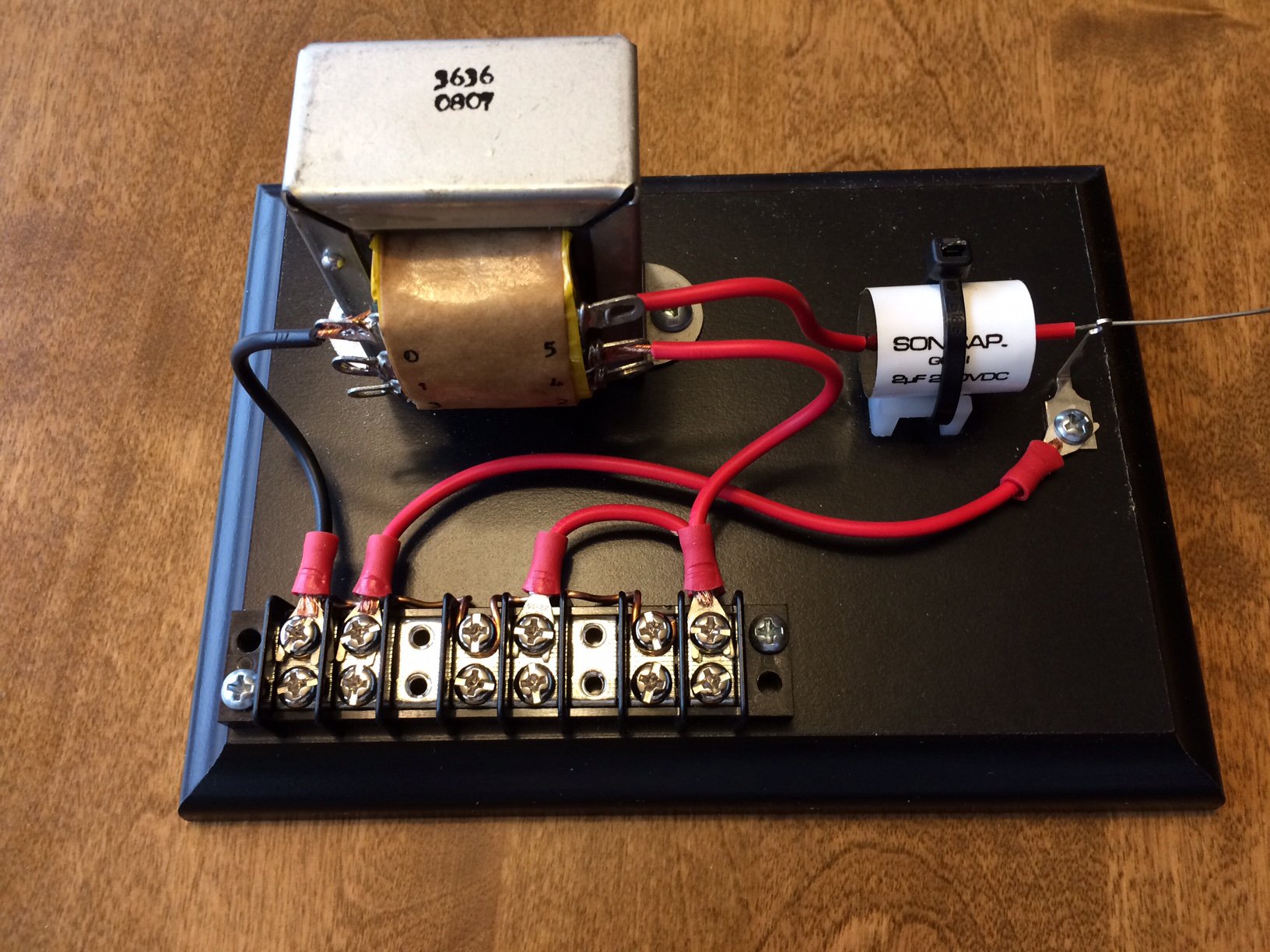
Not sure if this helps, but here's a Type-A-BA (bi-amp) crossover I'm working on. SInce the active crossover replaces the 2.5 mh inductor (low pass filter) and the 13 uf capacitor (high pass filter) of the Type-A crossover, all that remains is an autoformer and 2 uf cap. I even went so far as to reverse the function of the autoformer. Instead of attenuating the mid by 3 db, the autoformer passes a 3 db gain to the tweeter. Since I'm using the same amp type for the low and high pass, I run the low pass amp at full volume, and the high pass amp at around 12 o'clock. Mike
-
PM sent.
-
I've been curious about the Xkitz products too. If you are willing to do some DIY, I'd be happy to send you a pair of Marchand XM1's with 500 hz modules, as well as the power supply for them. They are unbalanced input/output only. Regarding Al's crossover, hopefully someone smarter than me will chime in. It appears that the ends of the 33uf cap are soldered to copper (?) posts. If one were to connect a 14 AWG wire with alligator clips to the two posts, would that not bypass the capacitor completely? Now the crossover will only passively split the high pass signal from the active crossover to the mid and high drivers. Mike
-
It shouldn't be that hard to bypass the hi-pass portion of the passive crossover and drive the mid/high drivers using the hi-pass of the active crossover. If you could post a picture/schematic of the passive crossover, we could find out. Mike
-
If your motherboard has SPDIF out pins, and you have an open slot, this works great. I have one on my ASUS motherboard. https://www.ebay.com/itm/SPDIF-Optical-and-RCA-Out-Plate-Cable-Bracket-for-ASUS-Gigabyte-MSI-Motherboard/273133351510?epid=1247152598&hash=item3f98043256:g:Lf0AAOSwUIFavPhf
-
The TDA7297 is a wonderful chip amp!
-
Hey Warren Yes, it is still available! Mike
-
OEM x overs and realistic component upgrade
mboxler replied to Alexander's topic in Technical/Restorations
I'm in the process of re-capping my H2's, even though the original caps measured very close to 2uf. However, I was surprised to find out that the ESR measured from .85 ohm to 1.1 ohm on the originals caps. I then measured the inductor...4.17mh, but DCR of 1.6 ohms. I agree that inductors don't wear out, but I'm replacing it with a .22 ohm DCR inductor to see if the amp can better control the woofer. I'm curious if anyone else has measured the DCR on the original woofer inductors. Mike -
Has anyone tried the ALK Universal Economy crossover?
mboxler replied to kevinmi's topic in Technical/Restorations
Did Al make these universals specially for you or are these Bob's A-4500's? -
I'm sure this distance is buried somewhere in this thread, but using 48LR, at 400hz, introduces a 2.5ms/86cm delay times two, or 5ms/172cm delay. How many cm or inches does one add for the physical distance between the K-33 and the K-55 on a Khorn? Thanks, Mike
-
I had tested this before, thought I'd try again. I find this stuff fun, but I'm weird. I applied a 5.05 volt, 1160 hz signal to a dummy crossover (yes, I named it after myself). I picked this frequency because at 1160 hz, the impedance of the 6.66 uf capacitor I used = 20.6 ohms, and the impedance of the 10.3 ohm resistor I had across taps 0-4 should double. This would be the resonance frequency, the frequency at which the voltage across the load (taps 0-5) should be down 3 dB. 6.66 uf cap between input positive and tap 5 of autoformer. Wire between input negative and tap 0 of autoformer. Wire between tap 0 of autoformer and one end of 10.3 ohm resistor. Wire between tap 4 of autoformer and the other end of the 10.3 ohm resistor. Input voltage, 5.05 volts at 1160 hz Voltage across cap, 3.61 volts Voltage across taps 0 - 5, 3.66 volts Voltage across taps 0 - 4, 2.58 volts Now the fun part. The impedance of a 6.66 uf cap in series with a 20.6 ohm load is 29.135 ohms. The current of 5.05 volts thru a 29.135 ohm load is .17334 amps. .17334 amps thru a 20.6 ohm load (the capacitor) = 3.57 volts...pretty close to the 3.61 I measured. Voltage across taps 0-4 should be 3.61 * .707, or 2.55 volts...again, pretty close to the 2.58 I measured. This confirms to me that the autoformer (at least when using it to attenuate the K-55 by 3 dB), doesn't have much if any affect. Mike