JJkizak Posted December 28, 2017 Share Posted December 28, 2017 Who was the guy doing the shifting? JJK Quote Link to comment Share on other sites More sharing options...
babadono Posted December 28, 2017 Share Posted December 28, 2017 if'n you can't find 'em grind'em. 1 Quote Link to comment Share on other sites More sharing options...
CECAA850 Posted December 28, 2017 Share Posted December 28, 2017 2 hours ago, USNRET said: Engine drives Reduction Gear Box where different ratios are involved to drive the propeller (13.54:1 for a prop speed of 1080) and the idler gear that failed spins other ratio gearing for the other accessories. That's quite a PTO you've got there. Quote Link to comment Share on other sites More sharing options...
tigerwoodKhorns Posted December 28, 2017 Share Posted December 28, 2017 3 hours ago, USNRET said: Looks like you threw up on your pillow. Quote Link to comment Share on other sites More sharing options...
Moderators dtel Posted December 29, 2017 Moderators Share Posted December 29, 2017 Don't know what the problem was but there sure was one. 1 Quote Link to comment Share on other sites More sharing options...
USNRET Posted December 29, 2017 Author Share Posted December 29, 2017 25,000 hours on that gear. This is only my second time since 1977 to have this happen. This first time was during engine start at Clark AFB in the Philippines in the '80s. Quote Link to comment Share on other sites More sharing options...
Woofers and Tweeters Posted December 29, 2017 Share Posted December 29, 2017 9 hours ago, USNRET said: 25,000 hours on that gear. What does the mating gear, other gears and bearings look like? Has metal been going through those parts for a while, or a sudden failure on that one gear? Quote Link to comment Share on other sites More sharing options...
USNRET Posted December 29, 2017 Author Share Posted December 29, 2017 58 minutes ago, Woofers and Tweeters said: What does the mating gear, other gears and bearings look like? Has metal been going through those parts for a while, or a sudden failure on that one gear? It'll be a few months to get it torn down and inspected. Quote Link to comment Share on other sites More sharing options...
JL Sargent Posted December 30, 2017 Share Posted December 30, 2017 This presentation includes an exploded view of the gearbox in question. https://prezi.com/p8jan1ldutcm/t56-a-14-turboprop-aircraft-engine/ Quote Link to comment Share on other sites More sharing options...
wvu80 Posted December 30, 2017 Share Posted December 30, 2017 OK, I'll go on record and be the first to admit I didn't know airplanes had gear boxes. @USNRETMichael, what were the consequences of the gearbox failure? Did the pilot disengage the GB and glide in? I know some planes can glide and some will drop like a rock out of the sky. By my admittedly amateur eye, it looks like the pilot was lucky to be alive after that kind of catastrophic failure. Quote Link to comment Share on other sites More sharing options...
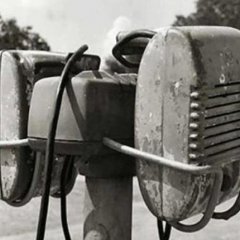
USNRET Posted December 30, 2017 Author Share Posted December 30, 2017 Depends on failure mode of the gearbox. You could lose the accessories (generator, starter, air compressor) or be catastrophic to the point of propeller coming off and penetrating the aircraft (has happened). There is no manual mode to disengage. There is a safety coupling designed to disengage when the negative torque (prop drives engine instead of engine driving prop)exceeds a preset value (-500 shp). This is for an engine failure to reduce drag. Won't know until the gearbox goes in for overhaul but it appears this was the crew's lucky day. The flight engineer (that is my background) recognized the failure and shut the engine down (feathered the prop) quickly. The engine was producing low thrust as they were very close to landing so descent created speed. FE pulled the emergency shutdown handle, pilot added power to other three engines, established a climb and brought the gear up. They completed emergency shutdown checklist and circled around for landing here at home. #2 engine normally powers main AC Bus A but when shutdown transfer relays move the load over to #4 engine which has a generator standing by. The P-3 flies just fine on three engines; in fact in the USN when patrolling we would shut down (loiter) #1 and then when fuel burn got us lighter we would loiter #4 and hang around the op area on two engines. On post flight it was discovered that the prop /engine could not be pulled through by hand (locked up) and when the prop was removed to change the engine we saw evidence of sudden stoppage. Looks like they got it shutdown just in time before something BAD happened. They were on there way to a remote site for missions but one of the crew members forgot their passport and had to return. View from the FE seat. You can see the E-Handles at top (yellow) Quote Link to comment Share on other sites More sharing options...
Woofers and Tweeters Posted December 30, 2017 Share Posted December 30, 2017 40 minutes ago, wvu80 said: and some will drop like a rock out of the sky. Those are called helicopters Quote Link to comment Share on other sites More sharing options...
Woofers and Tweeters Posted December 30, 2017 Share Posted December 30, 2017 6 minutes ago, USNRET said: There is a safety coupling designed to disengage when the negative torque So this is like an overrunning clutch? Ex: the engine can transmit torque to the prop, but he prop can't transmit torque to the engine? And does the propeller brake keep the prop from over speeding in a glide? Quote Link to comment Share on other sites More sharing options...
USNRET Posted December 30, 2017 Author Share Posted December 30, 2017 26 minutes ago, Woofers and Tweeters said: the engine can transmit torque to the prop, but he prop can't transmit torque to the engine? Correct. 26 minutes ago, Woofers and Tweeters said: does the propeller brake keep the prop from over speeding in a glide? No. The brake is there to help prevent rotation in flight when the prop is feathered. It also helps slow the prop when shut down on the ground. The brake is a cone shaped device (think of two ice cream cones, one inside the other). When starting the engine the starter pushes the two cones apart and then they are held apart by oil pressure. The propeller has a constant speed valve housing. The flyweights always want 100% (1020 RPM). Due to CTM (centrifugal twisting moment) the blades always want to decrease blade angle so there is almost always hydraulic fluid ported to the increase blade angle side of the prop dome. There is another forced called ATM (aerodynamic twisting moment) forcing increased blade angle but it is significantly less than CTM. 1 Quote Link to comment Share on other sites More sharing options...

Recommended Posts
Join the conversation
You can post now and register later. If you have an account, sign in now to post with your account.
Note: Your post will require moderator approval before it will be visible.